
Resolving a sensor error message
Inspecting the sensor cable and wire connections
If your ETC digital controller is responding different than it should, first check to confirm all your settings are correct (the manual shows how to access the settings and what they mean). If the controller is occasionally giving a wrong reading (or jumps suddenly), ensure that the sensor cord is not running parallel to the pump cord (keep at least 6” distance between), or other electrical cords (transient voltage jumps across wires and can interfere with the electronics, this is more likely with higher voltage lines or motors that have sudden inrush of power such as pumps); when the sensor wire must cross the pump cord or other wires, only do so at right angles.
To help diagnose an issue for resolving the error:
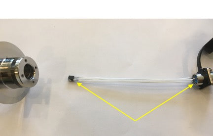
1) Unplug/replug the sensor connectors, and wiggle the sensor cable on both ends to see if that can change the reading. If one of the soldered wires is about to break from the soldering points, this method might help discover which end is deteriorating. For the sensor cable, one can measure the continuity of each pin between two ends. If there is a broken wire in the cable, the reading will be ‘OL’ for open line.
2) In general, one can try to isolate the problem by replacing one part (the cable, the sensor, or controller) at a time to isolate which part is causing the problem.
When the temperature controller (the ETC or touch screen) shows the message ‘ERR’ , ‘85’ or ‘185’ it normally means it is not receiving a signal. The most common cause of this message is a broken connection caused by rough handling of the sensor or twisting of the cable. A connection may be broken in either the sensor or the connecting cable. First, inspect the full length of the cable to ensure it does not show signs of crimping that may indicated a pinched or damaged cable which would need to be replaced. If the cable is fine, to inspect for a broken connection, follow these steps.
Sensor Cable
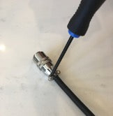
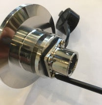
- Loosen the cord grip/strain relief clamp with a small Phillips screwdriver. (Do not completely remove the screws, just loosen them so the clamp does not grip the cable.
- With your index finger pushing down on the white (blue on older models) portion of the connector, and two fingers of one hand gripping the collar (to hold the top portion secure), with the other hand unscrew the collar (lower portion) from the connector.
-
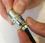
Move the collar down the cable and inspect the soldered cable joints. They should be intact. A broken connection will be easy to spot as an unconnected wire. If the wires are detached and need to be resoldered, the correct pin assignment can be confirmed by looking at the other end of the cable and matching the color of each wire to the number of the pin. The factory default is pin 1 is for the yellow ground wire, pin 2 is for the black positive wire, and pin 3 is for the red signal wire.
- Reattach the collar with the above steps in the reverse order. Ensure that the cable and cord end are not twisted when reinstalling as this can put tension on the solders; only the collar should turn. And when retightening the cord grip on the collar, ensure that the cable is snug and cannot move under the cord grip. Over time the cable jacket might age and shrink so a small amount of heat shrink or electrical tape may be needed under the cord grip so that it snugly grips the cable.
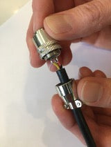
- When attaching the cable to the sensor or controller, turn the cable by gripping the collar and cord grip and turn the collar in a clockwise direction until the slot/pins line up. Turning in a CCW direction could put strain on the solder points as it will unscrew the inner portion (Locktite could also be applied to those threads but of course would then be harder to open if you needed to repair). Do not pull on or twist the cord and keep the cord in a flat/uncoiled manner when connected (a coiled cable could turn the collar in a CCW direction putting strain on the solders, as well as posing a tripping hazard). Being a small, portable, cost-effective electronics cable, it is more fragile than the larger, bulkier power cables, and more prone to breakdown than a non-portable, non-removable, permanently wired and permanently fixed cable, but with care, should last many years.
Sensor
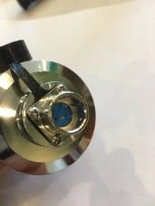
- Inspect the three pins to ensure they are not bent or broken.
- Loosen the four screws with a small Phillips screwdriver.
-
Gently slide the sensor out and inspect the wire joints at the connector end and at the sensor end. An unconnected wire will cause the sensor to malfunction. The compound on the sensor is heat transfer
compound and should not be removed as it facilitates faster temperature reading.
- The sensor is a small computer chip and should be treated carefully as one would a computer (ie. don’t be rough with it and don’t place it near a magnet).