
Assembly of the BIAC is relatively intuitive and straightforward and the smaller units can be installed and ready to brew in less than 30 minutes. A brewer may want to substitute or alter a few parts, which is entirely acceptable, but this description explains how to assemble it in the typical manner. The BIAC being shown here is the Small version; Small, Medium and Large models are almost identical. The Microbrewery 4-in-1 conical fermentors (MB) are almost identical to the Homebrewery 3-in-1 conical fermentors (HB) for almost all aspects of the installation. The 1.5BBL brewing system, 3BBL brewing system, 5BBL brewing system and 7BBL brewing system are almost identical to the Small 5 gallon brewing system, Medium 10 gallon brewing system and Large 15 gallon brewing system, except that they have a few more pieces.
Note: Watch BIAC brewing equipment complete brewery installation video here.
|
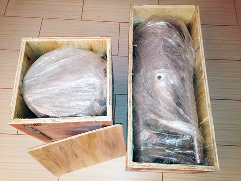
1. The BIAC will arrive in two wooden crates. The fermentor (3-in-1 conical fermentor with Homebrewery systems and 4-in-1 conical fermentor with Microbrewery systems) in one and the Mash Colander in the other. Remove the screws and withdraw the vessels. The fittings and accessories are packaged inside bags inside the vessels or in separate boxes. Before emptying the fittings out of the bag, look at the packing list inside the bag as it will help you identify where the fittings from that bag should be installed.
|
 |
 |
2. The fermenter is shipped without the casters installed to prevent damage in transit. To install the casters for the Small, Medium and Large fermenters, first lock the wheel which will allow the bolt to be turned in manually. To install the 1.5-7BBL BIAC, first install your hoist. Installing the hoist and gantry is a two person job, especially if you get a steel 4000lb gantry as it is quite heavy. You might even want to use a forklift or scissor lift to position the gantry and hoist while it is assembled. The casters on the 1.5BBL 1HL conical fermentor, 3BBL 3HL conical fermentor, 5BBL 6HL conical fermentor, and 7BBL 8HL conical fermentor models attach with four bolts. The fermentor can be lifted up with the hoist and casters installed. .
|
|
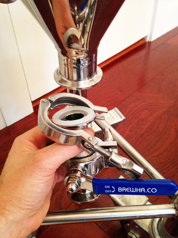
3. Attach the first of the four sanitary valves (five with the 1.5-7BBL 4-in-1) to the bottom port of the fermenter by placing a gasket between the vessel and the valve and attaching a clamp. Use the large valve here if you purchased one. The valve can be in either direction and it will not affect performance. (With the large valve and the Small fermenter, the handle may need to turn up to fully open the valve.) Tighten the valve clamp manually until it is snug. Over-tightening (e.g. with a tool) could damage the silicone gasket. (It is good to fill the fermenter with water to check for leaks before each brew day. If a valve is leaking, sometimes wiggling the handle and tightening helps, or the valve may need to be reassembled.) During fermentation, the brewer can dump yeast/trub out the bottom port when primary fermentation is ending (after about 3-4 days with ales) to prevent the yeast 'cake' from getting too hard (be sure to rinse the port well with sanitizer after dumping so that microbial growth doesn't occur).
|
 |
 |
4. There are 2" TC ('TC' stands for Tri-clamp or Tri-clover compatible fittings which are very common in sanitary applications) and 1.5" TC ports on the cone of the fermenter. The 2" TC ports are for heating elements (one each on the Small to Large, two on the 1.5BBL, four on the 3BBL, six on the 5BBL, and five 3" on the 7BBL). The uppermost 1.5" port on the side of the cone is for the temperature sensor. The middle 1.5" port on the side of the cone is for a valve (since it sits above the level that trub/yeast settles during fermentation it can be used to transfer/rack beer to kegs, although other ports can be used as well). The lower 1.5" port on the side that only opens into the jacket (it doesn't open into the fermenter) is for chilling water to enter the jacket (see Step 5). The bottom port on tip of cone was described in step 3 above. The Microbrewery 1.5BBL-7BBL models have a fourth 1.5" port on the side right above the bottom to which a valve can be attached for connecting a serving hose, as well as a 1.5" inlet on the lower side of the cylindrical portion of the vessel to which a valve or sight glass can be attached (can be used as a sampling port or for other purposes). |
|
5. If using municipal water for temperature regulation, attach the Temperature Control Valve water solenoid (TCV) to the 1.5" port on the side of the cone that opens only into the jacket of the fermenter, not the main body of the fermenter. The TCV is used to shut off chilling water going into the jacket to cool the wort after boiling, and during fermentation (if using tap water) so doesn't need to be installed until after the boil is completed. The power cord on the TCV should be plugged into the 'C' receptacle on the Electronic Temperature Sensor and Controller (ETC). (If using warm water to warm the fermenter, connect the TCV to the 'H' receptacle on the ETC). The Water Pressure Regulator (WPR) should be installed either before or after the TCV (depending on whether you purchased the WPR with garden hose or tri-clamp connectors) to ensure that water pressure does not exceed the design limit of the jacket. During fermentation, if using the Brewery Wort and Beer Chiller to maintain fermentation temperature, the TCV should be removed and the Chiller pump (or the main Chiller power) plugged into the ETC instead of the TCV. When the fermenter needs chilling, the ETC will power the Chiller pump instead of the TCV to let cool water circulate through the jacket. |
 |
 |
6. Attach the temperature sensor (thermowell or liquid-tight sensor) through the upper 1.5" port in the side of the cone. |
|
7. Install the heating element and gasket on the larger, 2" port on the side of the cone. Install the element with the slot on the outer cap of the guard facing down (so it will drain wort if there is a leak). The 7BBL has five 3" ports to connect the heaters to. See this link for more stainless immersion heating element details and instructions. |
 |
 |
8. If you are using municipal water, connect a hose to the upper jacket port and run to a drain. It is strongly recommended to never close or impede flow out of the fermenter jacket in any way, and to have a high quality, high-temperature kink-resistant hose attached to the jacket exit port, so that pressure does not build up in the jacket and damage the vessel. For closed-loop chillant circulation (e.g. through a chiller during fermentation) connect your Chiller return hose to this port and run it back into the Chiller water reservoir. (All flow out of this port should be unimpeded in order to prevent any pressure buildup; the jacket is designed only to withstand less than 5psi pressure (7psi in the 1.5-7BBL). A Water Pressure Regulator can also be purchased that will add a measure of safety and should be installed to the water line going into the jacket. The regulator has an arrow etched on the side, showing the direction of flow—install it with the arrow pointing towards the fermenter jacket.) |
|
9. Attach the Pressure and Vacuum Safety Valve to one of the 1.5" lid ports. When ready to rack beer to kegs, remove the relief valve and attach the 1.5" TC x 1/4" NPT half coupling fitting. This port can then be used to attach a 'gas in' post to apply 1-3psi CO2 (do not exceed 3psi inside the main body of Homebrewery 3-in-1 fermenters; 14.9psi in the Microbrewery 4-in-1 models) to help rack (transfer) your beer to kegs (using just gravity can be done but will introduce oxygen into the fermenter and the top of keg will have to be situated below the bottom of the fermenter). Each gas post is different for different makes so will be easiest for interchanging in the brewery if a post is purchased that is identical to the keg posts. Adapters to connect the 1/4" half coupling to the gas post can be found at most major beer ingredient supply stores (for corny ball lock kegs, it is a 1/4" to 19/32 adapter). Here is one source for adapters. (See point 11 below regarding blow-off hose.) The 1.5-7BBL MB models have a large 6" center ferrule for the Brewery CIP assembly and adding hops; install the 6" gasket, cap and clamp to that port. |
 |
|
|
10. If planning to use CO2 to rack beer to kegs, attach a valve to the port on the lid to close it and allow 1-2 psi of pressure to build up when racking your beer—ensure the valve stays open during fermentation to avoid any buildup in pressure in the vessel which is designed to hold less than 3psi (14.9psi in the MB models), or better yet, only install the valve (or a cap) when ready to transfer your fermented beer into kegs. If there is any risk of someone accidentally closing the valve during fermentation, remove the handle once in the open position. (If not using CO2 to rack, only a hose barb needs to be attached here, but be sure to remove the hose from your blow-off cup when chilling or racking as water will be sucked into your beer as you drain beer out the bottom of the fermenter. See step 11.) |
|
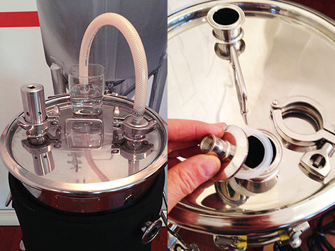
11. Attach a 1/2" hose barb to the top of the lid valve. If not using CO2 to rack, the hose barb can be attached directly to the port (the picture to the right shows a valve inserted between the fermenter and the blow-off hose, but the valve is only used when transferring finished beer out of the fermenter and otherwise should always be left open; how to install without the valve is shown in the picture with step 9 above). A blow-off tube (section of 1/2" tube) should be attached to the hose barb and the other/distal end placed in a bucket, jar or glass of water (and Star San) to allow gas produced during fermentation to escape. The longer pump hose (if purchased) can be repurposed but be sure to sanitize it first (rinse it well and place it for 5 minutes in a pot of boiling water). With the distal end of the hose in water, it forms a trap to prevent flies or bacteria from entering the fermentor. The picture in point 9 above shows the end of the hose in a glass on the fermentor, but where practical, it is recommended to use a longer hose and place the bucket, jar or glass on the floor so that if a small vacuum is created during fermentation, the water will not be sucked back into the fermentor. When crash cooling or otherwise cooling more than a degree or two, be sure to remove the hose from the water or the water could be sucked up into the fermentor. |
 |
|
|
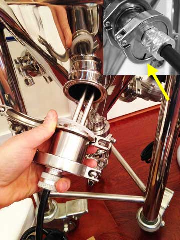
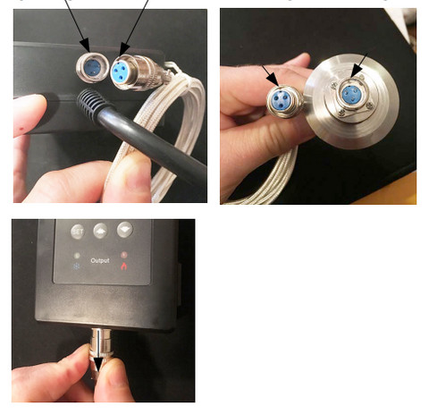
12. Connect the temperature sensor to the ETC by aligning the slot and pushing it on. Failure to align the cable and controller/sensor will likely result in damage and failure to operate correctly. The cable can be removed by pulling down on the collar as shown in the lower picture at left. The ETC can be placed on the fermenter or hung from a wall. Be very careful when connecting the cable as the pins can easily bend and break if not connected properly. The full ETC manual can be read by clicking here. |
|
13. An analog/dial thermometer can be inserted into a thermowell instead of the ETC temperature probe for non-electric reading of temperature.
|
 |
|
|
14. Hang the stainless water level ruler over the side of the fermenter when mashing and boiling. Remove the ruler before sealing the fermenter lid during fermentation. |
|
(Steps 15 and 16 are for installing the March Complete Pump Assembly) 15. If using a March 815 Pump Assembly (comes with Small-Large systems; the 1.5-7BBL comes with a much more powerful 7S pump that already has tri clmamp connectors, but will need power connected by an electrician—the power cord and cord grip are included and cord end is on the Power Controller), wrap the NPT male threads with teflon plumber's tape (tape five times around in the same direction as you would tighten a nut) and attach couplings (if you encounter a persistent leak, try adding NSF food safe teflon pipe dope to both threads, then taping). The wider (3/4" ID) braided, food-grade, high-temp silicone hose can be then connected from the bottom valve on fermenter to the inlet port of the pump (3/4" on the March 815 pump). If the line is plugging due to too much grain entering, it should be connected to a side port on the cone and the grain that falls through the Colander false bottom can be removed from the bottom of the fermenter and brought to the top of the Colander manually. The long, narrower hose (1/2" ID) should be connected from the outlet (1/2") port of the pump (or to a valve attached to the exit port on the pump; see step 16) and the other end to the inlet port of the Mash Colander (or sanitary valve attached to this port; see step 16).
|
 |
 |
16. A valve should be installed either to the top (outlet) port on the pump, or to the inlet port on the Mash Colander (shown in picture to the left), whichever is easier to access. Install the Mash Colander 90° hose barb to the inside port on the Mash Colander and attach a short hose (60-90cm/2-3') to direct the wort back into the top of the Mash Colander. When recirculating wort (out the bottom of the fermenter and into the top of the Colander), it is important to throttle (partially close) the valve on the Mash Colander so the pump doesn't withdraw wort too quickly (never throttle on the inlet side of the pump as this can wreck the pump by causing it to overheat). If the pump withdraws wort to quickly, two things can happen; first, it creates a pressure differential which pushes the grain down inside the Colander, plugging the false bottom, leading to a 'stuck mash' where the wort cannot flow at all and second, in extreme cases, the wort will drop so low that the element is exposed and on high power, could melt the element. The wort level should stay almost constant throughout the mash period—if it starts to rise, you know that the pump is moving wort too fast and should close the valve further. If wort is not passing through the Colander at all, it means the mash is stuck and it needs to be stirred up again and the filter bed reformed; if your mash sticks a lot, try a larger crush size—0.042-0.045" is recommended—or the use of rice hulls mixed in with the grain). As a general guide (will depend on several factors so adjust as necessary for your particular situation) recirculation in the Small BIAC should not exceed a rate of approx 0.5-1L/min, the Medium should not exceed 1-2L/min, the Large should not exceed 3-6L/min, the 3BBL should not exceed 5-10L/min, the 5BBL should not exceed 8-16L/min and the 7BBL should not exceet a cirulation rate of 15-20L/min. The pump can move liquid much faster than recommended so should be throttled back considerably during recirculation/vorlauf. This blog has more information on preventing a stuck mash. |


And that is it—happy brewing!! (Have any questions? Feel free to contact us anytime using the form below.)
Video: installing your BIAC complete brewery equipment
BIAC instruction manual